Hoosac Water Quality District
667 Simonds Road
Williamstown, MA 01267
_2013-10-30_231523.jpg)
Screening (Wet Well)
Influent wastewater from the interceptor arrives at the WWTF via an influent channel upstream of the influent wet well. The channel is outfitted with a mechanically cleaned screen. This screen has a 1.5-inch clear space between the bars to remove large solids from the incoming wastewater via a chain-driven rake mechanism. The rake mechanism lifts these large solids approximately 25 feet to the upper level of the building where they are discharged into a dump truck in the adjacent truck bay. A second channel, which allows flow to by-pass the mechanically cleaned screen, is provided with a manually cleaned bar rack.

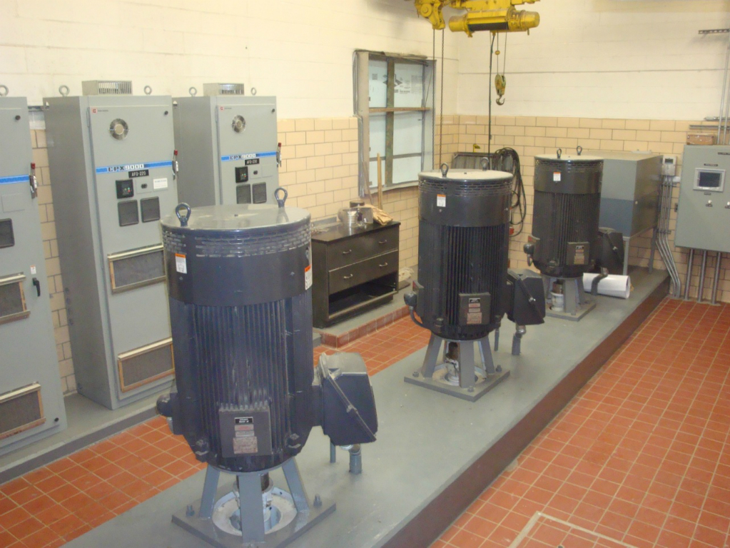
Influent Pump Room
The influent pumps accept the screened wastewater and transfer it to the aerated grit chamber (AGC). Each pump is capable of pumping 9 million gallons per day,(MGD) with a total capacity of 27 (MGD). These pumps are equipped with extended shafts that permit the motors to be situated on the upper building level, protected from damage in the event of drywell flooding due to a pipe or pump failure.
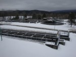
Aerated Grit Chamber
Following screening, raw wastewater is pumped to the aerated grit chamber (AGC). Two 7.5-horsepower blowers supply air to the chamber through an air header at the bottom of the tank, where the air is discharged through a series of diffusers. The air provides agitation to maintain suspension of organic material, while allowing denser grit to settle. The aerated grit chamber is intended to remove heavy, dense solid material such as sand, gravel or other materials that might damage mechanical equipment or settle out in low velocity sections of pipelines or tanks where removal is difficult. Settled material is removed from the AGC using a clamshell and hoist arrangement and is conveyed into a dump truck for disposal.

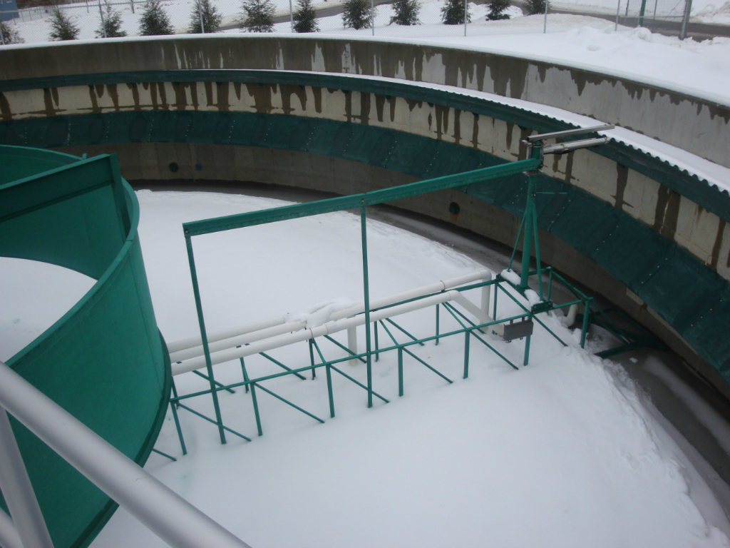
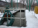
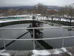
Primary Clarifier
The existing primary treatment system consists of two circular clarifiers, each 75 feet in diameter. Settled primary sludge is transported to the hopper near the center of each clarifier via a rotating collection mechanism. The sludge can be removed from the clarifiers via any combination of the six existing primary sludge pumps that are housed in the primary pump gallery. The primary sludge pipelines exiting each primary clarifier are equipped with in-line grinders to protect the pumps from damage and clogging by grinding large or stringy objects. The primary sludge pumps discharge directly to the existing belt filter presses during the dewatering process.
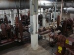
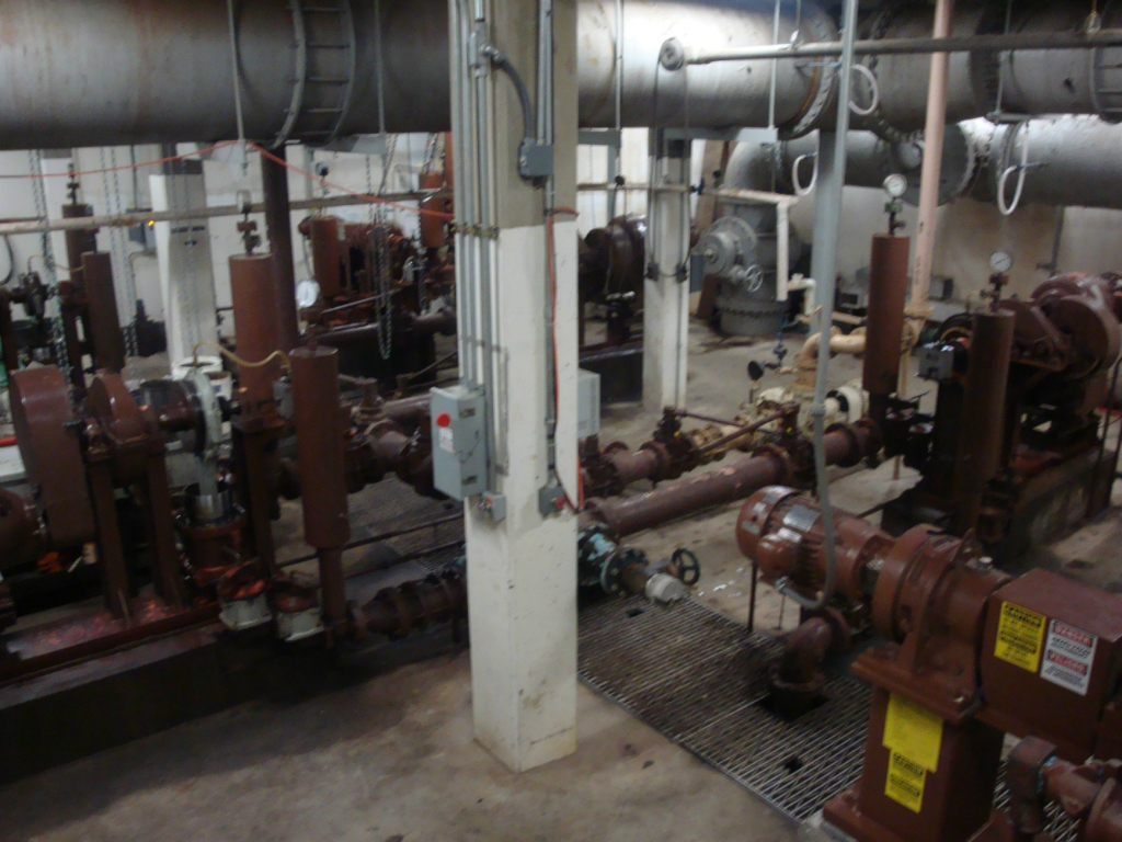
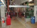
Primary Pump Gallery
Flow of the wastewater is overhead in all of the grey piping
All of the brown equipment is the six primary sludge pumps.

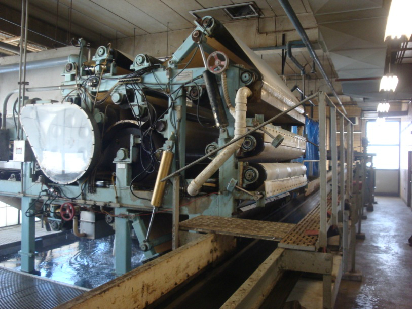
Sludge Belt Filter Press
As the co-settled sludge travels through each belt filter press, it undergoes gravity drainage in a rotating drum at the upper level of each machine. Following the gravity thickening section of each press, the thickened sludge feed is channeled between two belts and undergoes compression through a series of rollers to squeeze as much water out of the sludge as possible. The filtrate removed in the gravity and belt sections is collected in the sub-drain area beneath each press, where it flows through a network of process piping to the filtrate wet well.
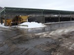
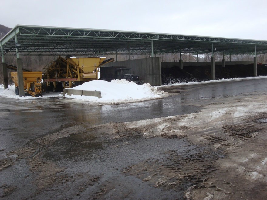
On-Site Composting
Following the dewatering system, sludge cake is transferred to an on-site composting facility, where it is stabilized for beneficial reuse. The on-site composting facility was originally constructed in 1983, upgraded in 1992, and expanded in 1997. Prior to 1983, co-settled sludge was dewatered using vacuum filters, and the dewatered sludge was hauled off-site for landfill disposal.
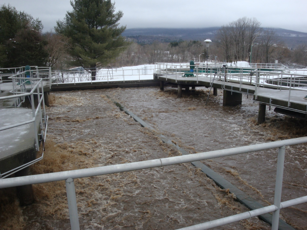
Aeration Tank
Following primary clarification, primary effluent flows to the two aeration basins. The aeration basins are configured to operate in parallel. Each aeration basin has a volume of approximately 717,000 gallons . Four, 30 horsepower mechanical surface aerators are bridge-mounted at quarter points in each of the two aeration basins (8 total aerators). These mechanical aerators serve two purposes, to mix the basin contents and transfer oxygen from the atmosphere into the wastewater.
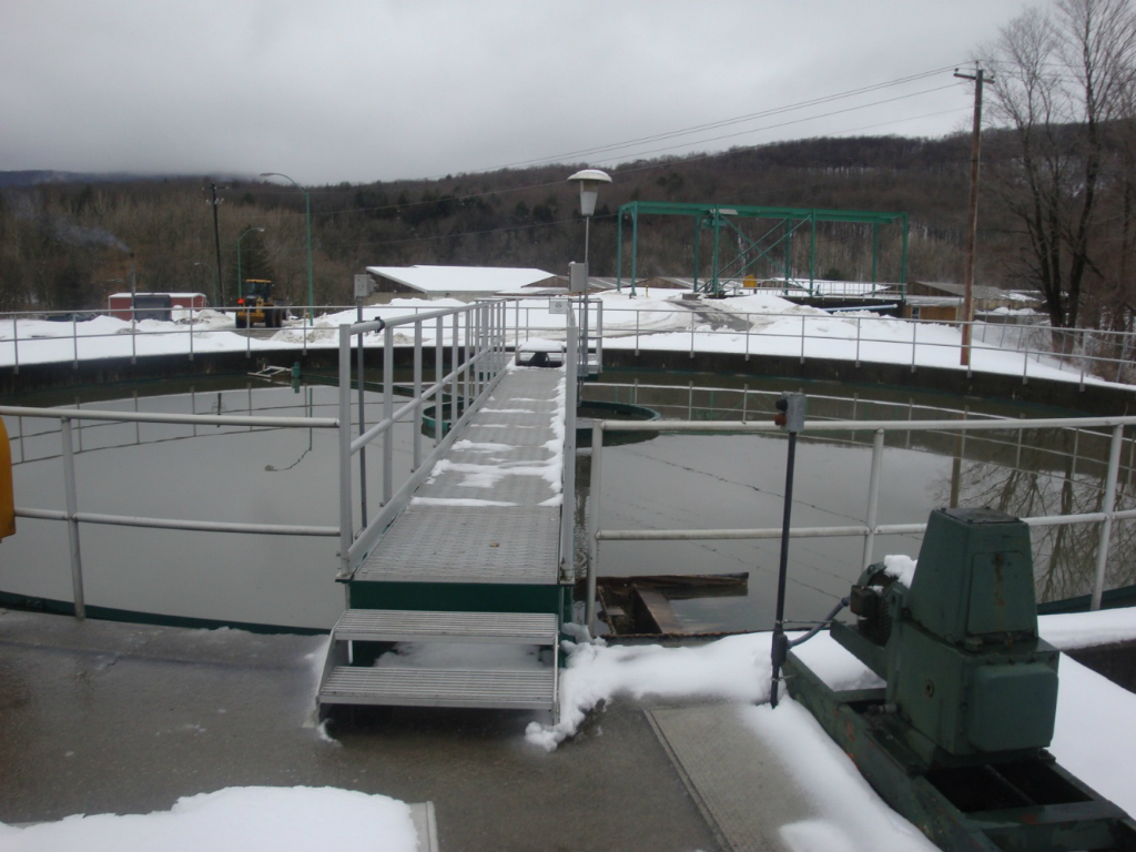
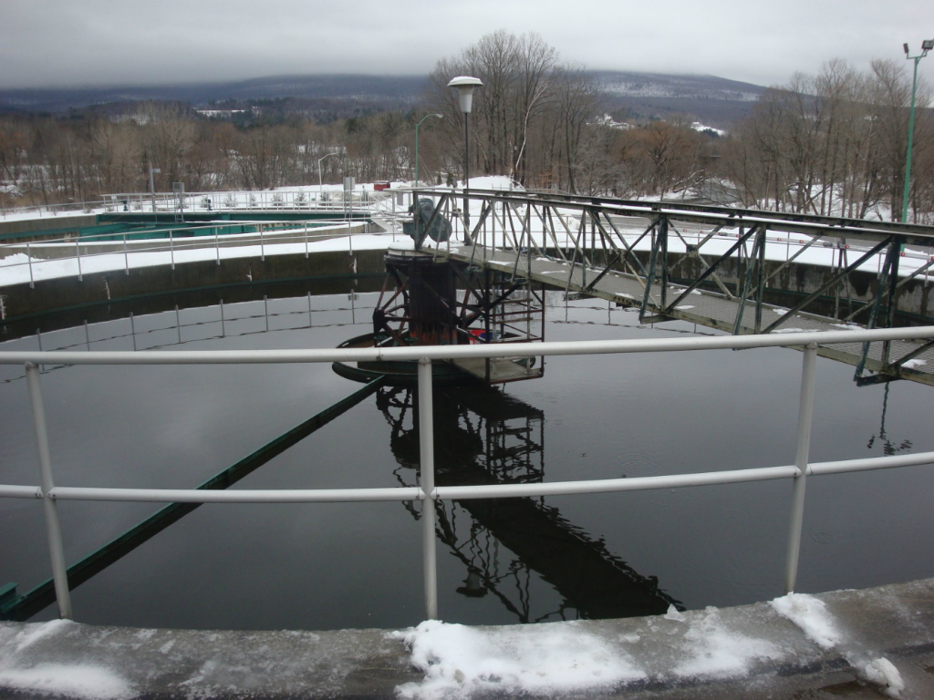
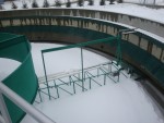
Secondary Clarifier
After undergoing aeration, mixed liquor from the aeration tanks travels through piping in the Secondary Pipe Gallery to three 85-foot diameter, center-feed, secondary clarifiers. Clarified effluent exits the secondary clarifiers via a series of v-notch weirs along the perimeter of the clarifiers and discharges to piping connected to the chlorine contact chambers.
April 1st to October 31st the District is required to disinfect the treated effluent. Sodium Hypochlorite and Sodium BiSulfite is used in our disinfection system.
Secondary Pipe Gallery
All equipment in the secondary pipe gallery including, RAS pumps and piping, WAS pumps and piping, RAW wastewater piping and all associated electrical wiring was replaced during the upgrade in 2008.
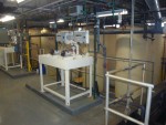
Sodium Hypochlorite
The existing disinfection system consists of a liquid sodium hypochlorite chlorination system and a sodium bisulfate dechlorination feed system housed in the lower level of the operations building

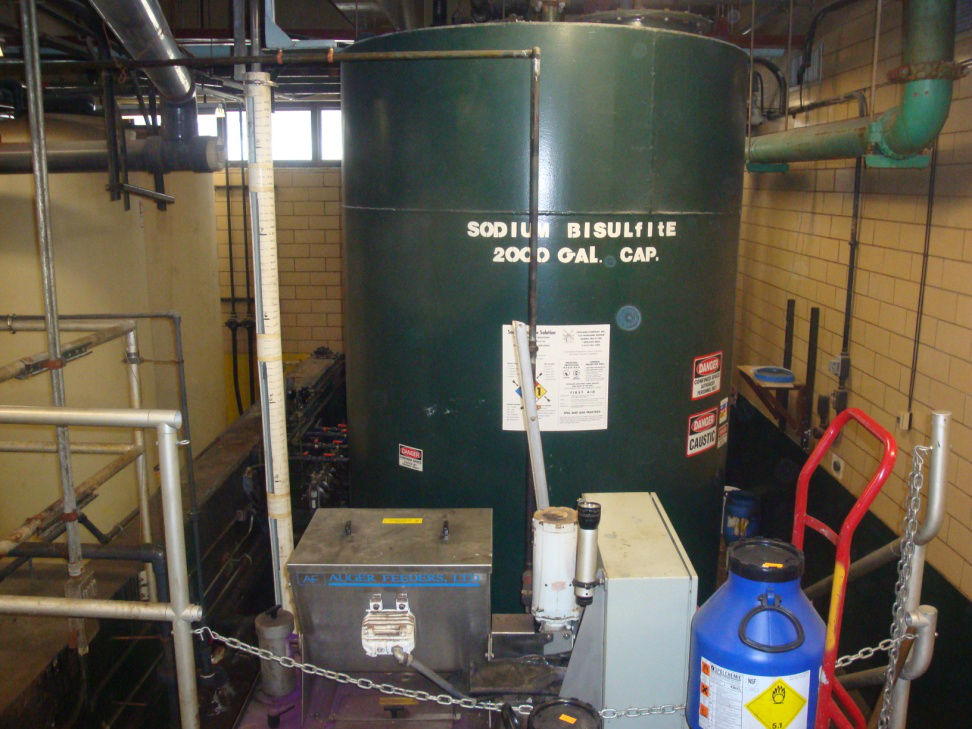
Sodium BiSulfite
The existing disinfection system consists of a liquid sodium hypochlorite chlorination system and a sodium bisulfate dechlorination feed system housed in the lower level of the operations building
Secondary Clarifier Rapid Return Piping
Return activated sludge (RAS) is collected through the rapid sludge return (RSR) system in each clarifier. The RSR system consists of a series of pipes extending from points along the radius of the rotating rake mechanism to the sludge collection chamber in the center of each clarifier. The collected sludge is then pumped to the aeration tank influent pipe for recycle, or pumped to the primary clarifiers for co-settling with primary sludge.
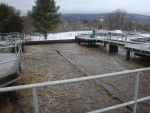
Chlorine Contact Chamber
The chlorine contact chamber (CCT) is configured in two parallel chambers that permit cleaning of one while the other remains in service. At the end of the two CCT chambers is a single dechlorination chamber consisting of a secondary weir structure below the CCT weirs.
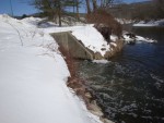
Outfall of Plant
The outfall is were the plant discharges the cleaned water to the receiving water, which is the Hoosic River
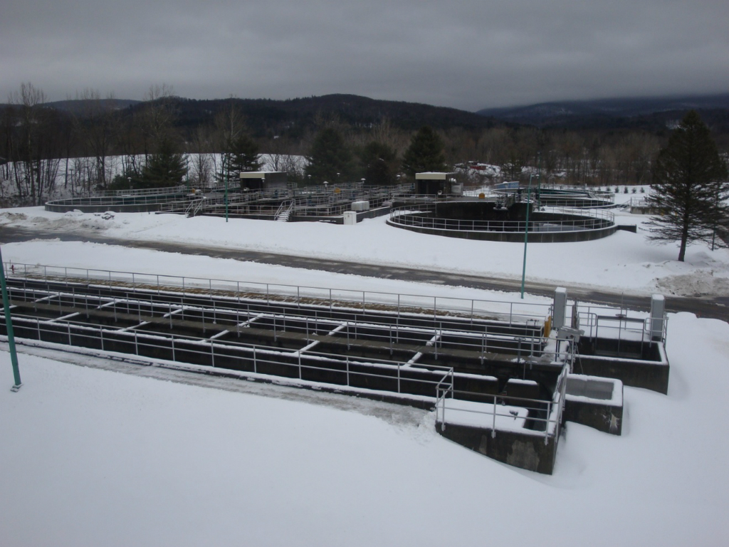
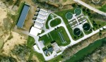
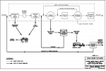
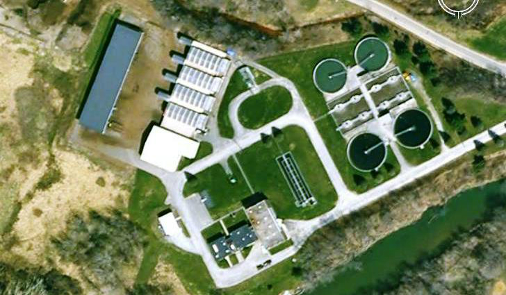
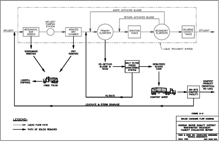
Treatement Systems Process
Screening (Wet Well)
Influent wastewater from the interceptor arrives at the WWTF via an influent channel upstream of the influent wet well. The channel is outfitted with a mechanically cleaned screen. This screen has a 1.5-inch clear space between the bars to remove large solids from the incoming wastewater via a chain-driven rake mechanism. The rake mechanism lifts these large solids approximately 25 feet to the upper level of the building where they are discharged into a dump truck in the adjacent truck bay. A second channel, which allows flow to by-pass the mechanically cleaned screen, is provided with a manually cleaned bar rack.
Influent Pump Room
The influent pumps accept the screened wastewater and transfer it to the aerated grit chamber (AGC). Each pump is capable of pumping 9 million gallons per day,(MGD) with a total capacity of 27 (MGD). These pumps are equipped with extended shafts that permit the motors to be situated on the upper building level, protected from damage in the event of drywell flooding due to a pipe or pump failure.
Aerated Grit Chamber
Following screening, raw wastewater is pumped to the aerated grit chamber (AGC). Two 7.5-horsepower blowers supply air to the chamber through an air header at the bottom of the tank, where the air is discharged through a series of diffusers. The air provides agitation to maintain suspension of organic material, while allowing denser grit to settle. The aerated grit chamber is intended to remove heavy, dense solid material such as sand, gravel or other materials that might damage mechanical equipment or settle out in low velocity sections of pipelines or tanks where removal is difficult. Settled material is removed from the AGC using a clamshell and hoist arrangement and is conveyed into a dump truck for disposal.
Primary Clarifier
The existing primary treatment system consists of two circular clarifiers, each 75 feet in diameter. Settled primary sludge is transported to the hopper near the center of each clarifier via a rotating collection mechanism. The sludge can be removed from the clarifiers via any combination of the six existing primary sludge pumps that are housed in the primary pump gallery. The primary sludge pipelines exiting each primary clarifier are equipped with in-line grinders to protect the pumps from damage and clogging by grinding large or stringy objects. The primary sludge pumps discharge directly to the existing belt filter presses during the dewatering process.
Primary Pump Gallery
Flow of the wastewater is overhead in all of the grey piping
All of the brown equipment is the six primary sludge pumps.
Sludge Belt Filter Press
As the co-settled sludge travels through each belt filter press, it undergoes gravity drainage in a rotating drum at the upper level of each machine. Following the gravity thickening section of each press, the thickened sludge feed is channeled between two belts and undergoes compression through a series of rollers to squeeze as much water out of the sludge as possible. The filtrate removed in the gravity and belt sections is collected in the sub-drain area beneath each press, where it flows through a network of process piping to the filtrate wet well.
On-Site Composting
Following the dewatering system, sludge cake is transferred to an on-site composting facility, where it is stabilized for beneficial reuse. The on-site composting facility was originally constructed in 1983, upgraded in 1992, and expanded in 1997. Prior to 1983, co-settled sludge was dewatered using vacuum filters, and the dewatered sludge was hauled off-site for landfill disposal.
Aeration Tank
Following primary clarification, primary effluent flows to the two aeration basins. The aeration basins are configured to operate in parallel. Each aeration basin has a volume of approximately 717,000 gallons . Four, 30 horsepower mechanical surface aerators are bridge-mounted at quarter points in each of the two aeration basins (8 total aerators). These mechanical aerators serve two purposes, to mix the basin contents and transfer oxygen from the atmosphere into the wastewater.
Secondary Clarifier
After undergoing aeration, mixed liquor from the aeration tanks travels through piping in the Secondary Pipe Gallery to three 85-foot diameter, center-feed, secondary clarifiers. Clarified effluent exits the secondary clarifiers via a series of v-notch weirs along the perimeter of the clarifiers and discharges to piping connected to the chlorine contact chambers.
April 1st to October 31st the District is required to disinfect the treated effluent. Sodium Hypochlorite and Sodium BiSulfite is used in our disinfection system.
Secondary Pipe Gallery
All equipment in the secondary pipe gallery including, RAS pumps and piping, WAS pumps and piping, RAW wastewater piping and all associated electrical wiring was replaced during the upgrade in 2008.
Sodium Hypochlorite & Sodium BiSulfite Disinfection System
The existing disinfection system consists of a liquid sodium hypochlorite chlorination system and a sodium bisulfate dechlorination feed system housed in the lower level of the operations building
Secondary Clarifier Rapid Return Piping
Return activated sludge (RAS) is collected through the rapid sludge return (RSR) system in each clarifier. The RSR system consists of a series of pipes extending from points along the radius of the rotating rake mechanism to the sludge collection chamber in the center of each clarifier. The collected sludge is then pumped to the aeration tank influent pipe for recycle, or pumped to the primary clarifiers for co-settling with primary sludge.
Chlorine Contact Chamber
The chlorine contact chamber (CCT) is configured in two parallel chambers that permit cleaning of one while the other remains in service. At the end of the two CCT chambers is a single dechlorination chamber consisting of a secondary weir structure below the CCT weirs.
Outfall of Plant
The outfall is were the plant discharges the cleaned water to the receiving water, which is the Hoosic River


_2013-10-30_231523.jpg)